|
|
Post by Blaine on Jan 29, 2012 19:39:08 GMT -6
They are only threading into plastic. ;D  The turn signals all thread into aluminium..... It's a machine screw. The bodies of the signals are chromed plastic.The original screws are self -tapping machine screws.I was stating what worked for me.  |
|
|
|
Post by zekkfett on Jan 29, 2012 21:31:44 GMT -6
My dad is an old pack rat, he has BUCKETS of screws and bolts and washers and nuts. I'm pretty sure over the years I've seen a few of the type I need, probably even the same length. I'm thinking they were brass though.... Hopefully with the right thread pitch.
|
|
|
|
Post by zekkfett on Jan 31, 2012 11:51:35 GMT -6
Ordered new Tires and Air Filters today from the superstore.
Shinko 712's, front and rear. Emgo filters.
|
|
|
|
Post by zekkfett on Feb 1, 2012 17:34:29 GMT -6
Went to the hardware store today and got new turn signal screws. M6 x 1.0 x 15 ; if anyone else needs that information. Also got M8 washers.
Also found that the rear brake switch was not engaging properly, due to a stretched spring. Simply figured out where it needed to catch and tied a zip tie around the spring, so it still has flex, but it will engage the switch now. Zip tie just limits the flex of the spring. Also, moved the brake pedal up a few notches on the shaft and adjusted the rear brakes, for now; getting new shoes soon.
Then took her for a ride. Ran like a champ. Adjusted clutch freeplay.
5000 RPM @ 55 MPH. Sound about right?
|
|
|
|
Post by Blaine on Feb 1, 2012 19:13:23 GMT -6
Also, moved the brake pedal up a few notches on the shaft and adjusted the rear brakes, for now; getting new shoes soon. Then took her for a ride. Ran like a champ. Adjusted clutch freeplay. 5000 RPM @ 55 MPH. Sound about right? Yep,RPM's right on the button.Did you know that there is a adjuster on the bottom of the pedal to adjust it up and down?  |
|
|
|
Post by zekkfett on Feb 1, 2012 21:00:42 GMT -6
If you are referring to the stop bolt, it was already all the way out. Just wanted to get it up a little higher. It was the easy solution. Only took 3 mins.
|
|
|
|
Post by zekkfett on Feb 18, 2012 8:36:09 GMT -6
Update - Bike is getting new tires and rear brakes, as I type.
Started working the other night with one of the junk turn signals I took off. Got a nice pattern cut out, trimmed and fit inside the signal, for the LED boards that I will be making. From the looks of it, I'm hoping to get 16-24 LED's per signal. Will be ordering LED's, diodes, resistors, and the breadboard from Ebay soon. I have pictures of the progress so far, but the GWK Image Host seems to be down.
The 2 patterns that I have, will work for every signal, as they are all constructed the same, the fronts just wired a tad differently. Toying with the idea of clear signal lenses on the back, with a ring of red LED's in the signals as a brake light. Maybe in future prototypes.
From calculations that I have done, each LED board will pull .8 amps, x 5 lights (4 signals and the brake/tail light) = 4 amps total draw at full output. This is less than just ONE of the 1157 bulbs in the tail light on just its parking light filament. With the brake light on, and one side of the turn signals going, all stock bulbs pull nearly 50 amps at full output.
If anyone would be interested, I would be willing to sell some sets on here, after I get a nice prototype working. All 5 pieces, prob in the range of $60-$75, just for you guys on here. These will be direct bolt in parts, no modding on your part. Pull the old bulbs out, mount my LED boards, put the lenses back on. If you have running/driving lights, or have any kind of other Medium-High Amperage draw electrical devices, this mod would be a must if you want to make that stator last. Along with an HID conversion. (Contrary to what a lot of people believe, HID's actually pull LESS current than a standard halogen bulb; with FAR more light).
If anyone would be interested, let me know; as I will order more LED's than what I will need for just my project. As soon as the image host is back up, I will post the pictures that I have on the progress so far.
|
|
|
|
Post by eaglerider on Feb 18, 2012 13:20:41 GMT -6
When u change to LEDs, u will most likely find that the stock electro-mechanical flasher will not work, or work right. You will have to swap the flasher for an electrical one, available at most auto supply stores....it is a direct plug-in replacement, and actually works better with stock lights, than the stock flasher.
|
|
|
|
Post by zekkfett on Feb 18, 2012 13:31:36 GMT -6
When u change to LEDs, u will most likely find that the stock electro-mechanical flasher will not work, or work right. You will have to swap the flasher for an electrical one, available at most auto supply stores....it is a direct plug-in replacement, and actually works better with stock lights, than the stock flasher. Yep, I knew that. If I offer the kit for sale, it will include a new flasher. |
|
|
|
Post by chopperfreak2k1 on Feb 19, 2012 5:03:04 GMT -6
well Zek my man, sign me up for 1 or 2 pairs of fronts and rears. sounds like you really worked it all out to me. thanks!
|
|
|
|
Post by zekkfett on Feb 19, 2012 11:40:28 GMT -6
Pics of the progress of the LED signals:  First paper template I made. Shaded areas are where there are not going to be any LED's, due to pieces inside the signal housing.  Cardboard template inside the turn signal lens.  Signal Assembled with template inside. Wanted to get a look at how it fit together, and to see if I could see where I'm not going to be able to have LED's.  Cardboard template inside the signal housing. As you can see there is a screw that is already inside the signal, so it will be 1 of the 3 mounting points; the other 2 will be the lens screws themselves. Below the screw is a "stud" that will also be used in the mounting process.  The junk signal I used, with the cardboard template. |
|
|
|
Post by zekkfett on Feb 19, 2012 11:51:33 GMT -6
well Zek my man, sign me up for 1 or 2 pairs of fronts and rears. sounds like you really worked it all out to me. thanks! Concept will probably take about a month, maybe a month and a half to properly design and build. (And have parts shipped in.) Once I have a good working prototype, pics will be posted. These are going to be LED replacements for STOCK type turn signals; Vulcan and 454. These are not going to be your average junk pieces auto parts stores try to sell you. They are going to be properly designed, and rated for ACTUAL voltage at highway speeds, not just for 12.6 volts; which is why most aftermarket LED setups burn out, or do not work properly. Pictures of the progress will be posted periodically. As I look at it more, I see that I might be able to get maybe 30 or more LED's in there. chopperfreak, if you can wait that long; I'll PM you some extra pics once I get a little further along. Don't worry, this isn't a project I'm just going to give up on, these will be built! Anyone else that is interested, get back at me. |
|
mradam
Junior Member

Posts: 214
|
Post by mradam on Feb 20, 2012 13:52:33 GMT -6
i would be interested in your schematics when done LOL. port this idea into my aftermarket housings.
|
|
|
|
Post by chopperfreak2k1 on Feb 20, 2012 20:26:30 GMT -6
yeah brother, i'm in no hurry at all. take your time and let us know what's what. i definetely appreciate your time and effort on this project!
|
|
|
|
Post by zekkfett on Feb 23, 2012 0:04:09 GMT -6
Update - Bike now has new tires and rear brakes. Haven't had the chance to ride it yet on them, but the twin has the same tires, so I know what to expect. My girl's dad picked it up from the shop with the trailer, and stashed it in his heated garage, so I haven't even seen it since. She also had her fork & dust seals replaced. Played around with a program, got a LED signal laid out on it.  (This would be the left-front signal, as you are looking at the bike from the front) This is based on a 2.75" housing, which I think the actual light is about 3". Based on 5mm LED's, it looks like there COULD be up to 105 LED's per signal. Full output: .42 amps @ 1,260,000 mcd. 45 degree viewing angle. We shall see once parts start arriving. If 105 LED's will truly fit in there, I DEFINITELY did not order enough LED's..... But I'm very much doubting it will be able to fit that many. |
|
|
|
Post by chopperfreak2k1 on Feb 23, 2012 0:38:55 GMT -6
looks promising. nice progress brother!
|
|
|
|
Post by zekkfett on Feb 23, 2012 0:59:08 GMT -6
Went back and played with the program a little, found out I had made a 5 1/4" light instead of a 2.75" light. Took me a minute to remember that radius is only half of diameter, so I had the radius in at 2.75" Time to make a new layout....
Probably about 40-45 LED's I would guess.
It's getting late and I'm crashing for the 15 hours tomorrow. Will redesign tomorrow in between jobs.
|
|
|
|
Post by zekkfett on Feb 23, 2012 1:00:23 GMT -6
looks promising. nice progress brother! Thank you sir! |
|
|
|
Post by chopperfreak2k1 on Feb 23, 2012 3:04:18 GMT -6
shoot, thank YOU for puttin in all this work. it is very much appreciated!
|
|
|
|
Post by kcoers on Feb 23, 2012 4:53:24 GMT -6
nice bike!!
|
|
hoosierrick
New Member
 looking for a complete tool box. PM ME
Posts: 46
|
Post by hoosierrick on Feb 29, 2012 19:24:04 GMT -6
I might have 2 or 3 turn signal screws. I didn't have a whole matching set, so I got stainless allen head bolts and washers at the hardware . Cost about $5.00
|
|
|
|
Post by zekkfett on May 3, 2012 7:48:05 GMT -6
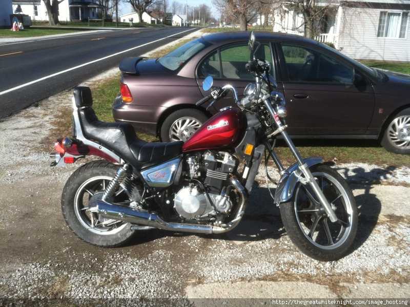
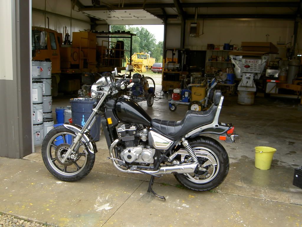
Bike has been hard to start the last few times. My first thought, "time for a valve adjustment". So I got to work here this morning and got to looking.....darn choke cable is broken. All in all; new tires, brakes, turn signals, and a couple cables; this old girl has treated me well; so far. Best mileage: 55mpg. Worst mileage: 49mpg. On 5 tanks full. Gotta love that, when the Saturn only gets 28mpg. Not quite as good as the Rebel, but still perfectly acceptable. As an update, I recently got a SpitFire windshield; works well enough. Took a WHILE to finally get it adjusted JUST right. For anyone looking into this shield, I have a couple pics to show how I have my mounting hardware, seems to be the best setup. Shield does SLIGHTLY touch the clutch cable, and 0-25mph isn't all that visible, but who needs speeds that slow?!? Move your head slightly forward and 0-25mph is perfectly readable.   And finally got a picture with my buddy's twin bike. It has recently had valves adjusted, starter & starter clutch rebuilt, new crankshaft end threads (tip: don't mess up the threads in the crank, the correct left-hand tap is COSTLY) & new right hand controls.  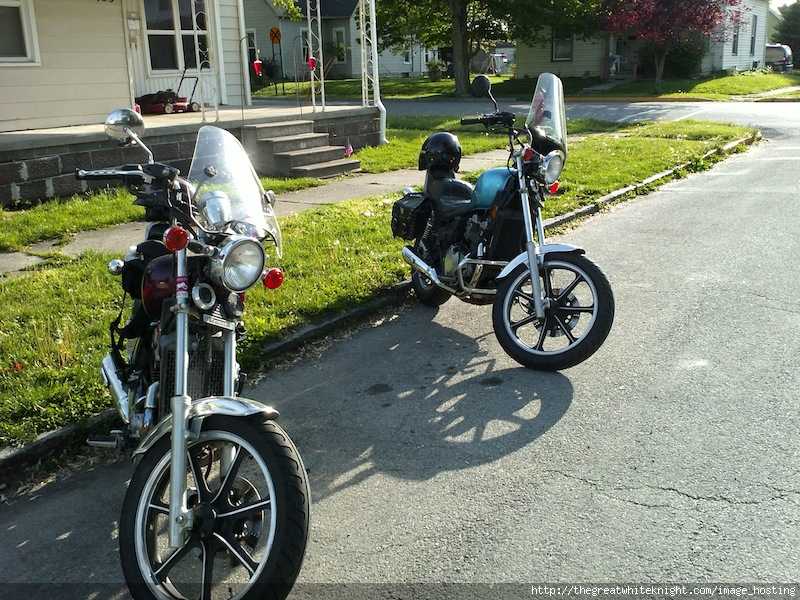 And lastly, my dad's new toy. (He got the fever after my buddy and I got our 454's.) He's getting older, and is VERY short.  |
|
|
|
Post by Jet⚡Black on May 6, 2012 12:45:30 GMT -6
Sure beats a Hoveround  |
|
|
|
Post by eaglerider on May 6, 2012 17:06:22 GMT -6
  ;D Got that right!!
|
|
|
|
Post by zekkfett on Jan 29, 2013 19:03:19 GMT -6
Finally!! Got to work on the LED conversion prototype last night. Made a prototype for a rear signal (no parking lights), using an old junk housing with a broken stem. The array uses 30, 5000mcd LED's, 6 100ohm resistors, and a 1 watt diode. The entire array only draws 2.4 watts and 180mA of power. Got the breadboard cut out, and the LED's soldered on.  Back side of the breadboard with just the LED's soldered on.  A couple views through the lens, at the LED's. These are the finished product. (In a junk housing, of course.)   All the LED's lit up behind the lens inside the turn signal housing. They are bright enough to drown out all the other ambient light so all you see is the LED's. This shot was taken with a 600 watt Halide lamp directly overhead. 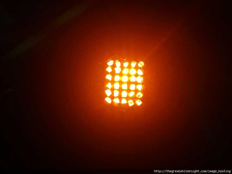 A shot taken from a 45 degree angle.  Shot taken from a 90 degree angle. (Those that know anything about LED's, know that LED's do not give off a great amount of light at extreme angles; and I'm getting a great amount of output even at this angle.)  And finally, the front side of the finished prototype. All parts installed. Not yet mounted to the housing.  Any questions, just ask. I'd be happy to help anyone with this project; just make sure you have the soldering skills (and a Dremel) to try to tackle it.  Future Versions to come. A ring of running and brake LED's in the rear turn signals is the ultimate goal. Probably going to try the Luxeon LED's as well. But for now, the brake light is what is of major concern to me. Probably going to go ahead and make a second turn signal tonight, but I'm going to turn my attention to making my brake light as visible as possible, as well as retrofitting some kind of small light to LED and mounting that on the toolbox as a second brake light. |
|
|
|
Post by eaglerider on Jan 30, 2013 14:33:03 GMT -6
;D I like!
|
|
|
|
Post by zekkfett on Jan 31, 2013 1:49:30 GMT -6
Thank you sir. That means a lot coming from you. Just a few hours after building, I had a nice self-critique of it, (I am my own worst critic) and I know a few areas where I'd do a couple things differently. Saw a few pics of some LED boards, and picked up a few ideas. But as I said, it's just a prototype for now. Probably going to run it for a while, see if I have an issues with it; while I'm working on the tail light prototype. I've got more than a few projects going on right now, and with 2 jobs, it's hard to find time. TOP on my list is a valve adjustment, but as it's too cold here to work in an unheated garage, it'll have to wait for the temp to come up. (I'm VERY jealous of you guys that get to ride year round....) Just under that in the to-do list, is a tire balance, then the brake light, the addition of a brake light to the toolbox, and an oil change. Then the plan is about 12,000 miles this year. I only got in a little over 3,000 last year due to some endorsement "issues". Speaking of projecs, as soon as the weather breaks, I'll have the valves to do on 3 bikes....  The only thing worse than not riding, is having to work on someone else's bikes.. ;D |
|
|
|
Post by zekkfett on Jan 31, 2013 1:56:41 GMT -6
Also, I need to source some 1156 and 1157 socket adapters. Just a simple socket adapter that will plug into the socket and give me the power wires off of it. I don't really want to break a perfectly good bulb to rig one up (although I will if I have to), I'd rather just have a nice, stock-looking adapter. Anyone that knows where I can pick some up at a good price, PLEASE, let me know.
|
|
|
|
Post by zekkfett on Jan 31, 2013 20:47:58 GMT -6
A little video I shot to demo it for you guys. Apologies in advance for the quality.... Shot with my Android phone in a dark room.
As I state in the video, a mistake was made regarding the diode in construction, and the computer power supply is only 12.1 volts; so the array is not getting to it's full brightness.
|
|
|
|
Post by Blaine on Jan 31, 2013 22:12:51 GMT -6
Great mod.They will look super!!! |
|


 ;D Got that right!!
 The only thing worse than not riding, is having to work on someone else's bikes.. ;D